

Mines safety bulletin no. 6 | 19 April 2000 | Version 1
Handling and management of surface trailing cables
1.0 Introduction
Trailing cables are utilised to supply a range of surface mining equipment including pontoon pumps, electric drills, draglines, shovels, crib huts etc. Typical voltages for trailing cables range from 415V to 22kV. Vast amounts of energy are carried within these cables.
High potential incidents involving trailing cables at surface mines that have occurred over the last 12 months include the following:
- A 6.6kV trailing cable plug developed a short circuit and completely disintegrated. This occurred after a rainstorm. Prior to this the shovel fed by the cable had walked and the plug was left lying on the ground in a depression where rainwater pooled. While no one was injured potential existed for serious injury had a person been in close proximity.
- When a 6.6kV cable was being moved arcing from the side of the cable was noticed. Internal insulation had failed and external arcing occurred due to a hole in the cable outer sheath at the site of a cable repair. Protection equipment did not operate to trip the supply.
- Machine operators attempted to uncouple live 6.6kV cables. They had mistaken an energised cable for one which had been previously isolated. Protection equipment operated to trip the supply; no one was injured.
- A trailing cable was damaged during relocation with a rubber-tyre dozer. The energised cable had excessive mechanical strain placed upon it by the machine. Protection relays operated to de-energise the cable supply.
- A 6.6kV trailing cable was pulled from its restraining plug as the cable was towed behind a cable boat by a dozer during a dragline relocation. Undue strain had been placed on the plug - no-one was injured.
- Reports have been made to the DME of persons driving light vehicles and mobile equipment over the top of cables.
A study of incidents reveals that the group of persons most at risk of injury from trailing cables are machine operators as they have the highest exposure to them while they are energised.
This discussion will be limited to handling, management and general operation of the cables. It seeks to raise awareness of the potential hazards associated with trailing cables at surface mines, principally high voltage cables, and highlight areas where attention may be required to ensure the risks are acceptable.
2.0 Potential Hazards
Potential hazards associated with surface trailing cables include:
- Uncontrolled release of energy - open arcing caused by insulation failure, explosion of equipment due to pressure rise inside apparatus caused by insulation failure (plugs). Potential injuries include severe burns, injuries resulting from being hit by projectiles and death. A 6.6kV dragline cable could typically contain enough energy to light 112,000 40W light bulbs. The pictures below depict a bolted 3-phase short circuit simulated inside a trailing cable plug and facial burns received from an energy release incident involving high voltage trailing cables.
- Indirect contact of a person with electricity - a person receives an electric shock not because they touch a live conductor, but because they touch a part that has become energised under fault conditions. An example of this would be a person receives an electric shock after they touch the outer sheath of a cable. The shock was received because of leakage current to the outer sheath due to insulation failure. Potential injuries include electric shock, burns and death.
- Direct contact of a person with electricity - a person touches an energised conductor in the cable. An example of this would be a person coming into contact with the receptacles inside an energised plug or touching a conductor inside the cable after it has been damaged. Potential injuries include electric shock, burns and death.
- Fire - the cable catches fire after a fault on the cable. Other equipment or the surrounding environment subsequently catches fire.
- Internal Energy Sources - biomechanical energy; ie. excessive forces placed on the body through manual tasks. Potential injuries include sprains strains and permanent disablement.
3.0 Potential Risks
While the photographs below are graphic, given normal operating conditions, the risks posed to a person by an energised trailing cable are low, however if the balance is shifted through:
- inappropriate work practice
- poor maintenance and repair standards
- inappropriate selection for use
- inappropriate operational standards and practice.
Then the risks may become unacceptable!
Injury, equipment damage or near hits may result, results depicted in the photographs may occur.
Any incidents, damage or injury are all indicators that the risks are not being managed as they should!
4.0 Typical Surface Trailing Cable Construction
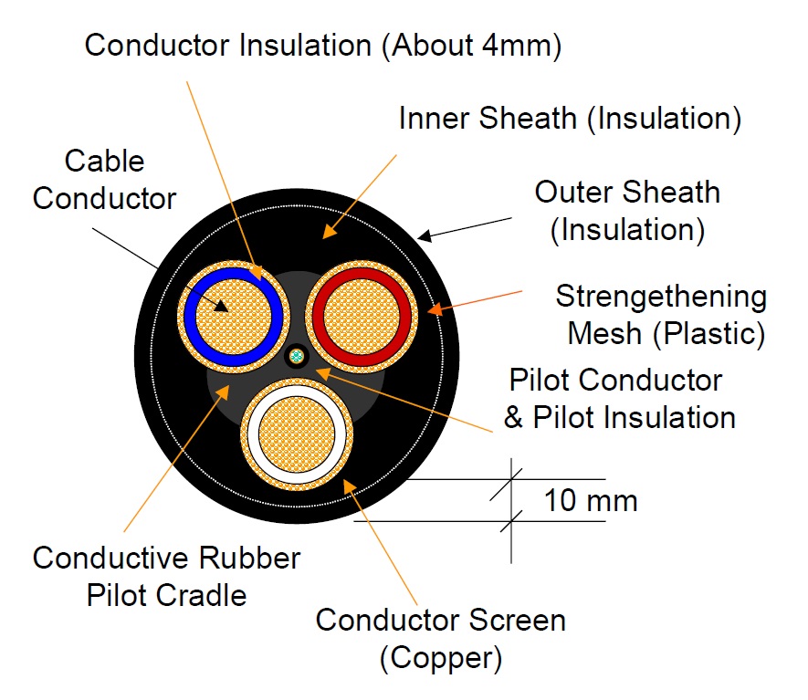
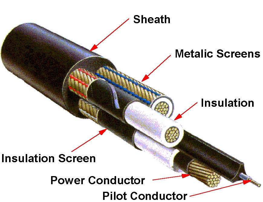
The diagrams below depict a typical high voltage trailing cable used to supply a dragline or shovel. The design of the cable is such that an earth barrier is placed between the conductors. This is to ensure that under fault conditions an earth fault will occur first thus ensuring the potential amount of energy released is reduced compared to a power conductor to power conductor fault (phase to phase). There is about 10mm distance between the outside of the sheath and the power conductor in a 120mm2 cable. Major components of the cable and their function are as follows:
- Power Conductor - Copper stranded and bundled conductors that deliver the energy to where it is required to be used. In a 120mm2 conductor they would be 15.6mm in diameter.
- Power Conductor Insulation - A rubber type insulating compound designed to contain the voltage to the confines of the power conductor.
- Cradle Separator - A cradle that carries the pilot wire at its center. The cradle holds the power conductors in their desired form and constitutes the basis of forming the cable during manufacture.
- Earth Metallic Screens - These screens completely surround each power conductor and are intended to carry fault current. They constitute the cable earth.
- Pilot Wire - A small conductor at the very center of the cable intended to be used in conjunction with protection relays to detect cable breakage during operation or prior to operation. The relay used will cause power to be de-energised in the event of cable breakage or plug separation while the cable is powered, or prevent power up if plugs are separated or the cable is broken (pilot wire broken).
- Sheath - A tough durable, hard wearing material designed to separate the power conductors from the external environment and allow the cable to operate and withstand physical and environmental conditions, which it was designed to endure.
- Semi-conductive tape - Used to separate the power conductors from the insulation and the insulation from the earth screens in cables with a higher voltage rating than 3.3kV. In cables with a lower voltage rating different materials are used for these barriers.
5.0 Typical Sources of Cable Damage
Typical sources of cable damage include the following:
- Machinery Damage - Machinery driving over cables including dozers, graders, light vehicles and equipment being towed across cables e.g. Lighting plants.
- Machinery Damage - Machinery striking cables, e.g. Grader blades, trucks striking cables with their bodies up as they cross beneath bridges.
- Machinery Damage - Draglines set shoes down on cable, draglines/drills/shovels propel over cable.
- Falling Rocks Strike and Damage Cable - Rocks from spoil piles, Falling rocks from buckets being swung over cables.
- Excessive Mechanical Strain - Too much cable attempted to be pulled in one drag, cables get caught on objects such as rocks and tear.
- Exceeding Minimum Bending Radius - Cables are only designed to be bent so far (check manufacturers guidelines for specifics).
- Wear Damage to Plugs - Wear to plugs and cable chaffing from being towed.
- Water Ingress into Plugs - Resulting from damaged plug seals or plugs left on the ground.
- Cables Used as Scrapers - When they are being towed rocks and dirt collect at the bottom radius bends.
- Poor Repair Standards - Repairs fail under service conditions.
- Cable Sheaths Torn/Punctured - Cable sheaths are torn and punctured by sharp objects such as rocks and dragline tub hooks, pin holes from sharp rocks allowing water and dirt ingress.
6.0 Recommendations
6.1 Every surface mine where trailing cables are in use should develop, implement and maintain a Trailing Cable Management System addressing the following as a minimum:
- Defined selection criteria addressing the application and the intended use for trailing cables.
- Defined standards for the operation of trailing cables includes the following:
- Regular inspection including in-situ visual inspection by machine operators.
- Regular testing of cables and maintenance of test records, definition of cable life cycles for each cable application and definition of measures to monitor and measure the life cycle criteria.
- Route criteria including support measures where applicable, methods and heights for crossings, identification measures for cables, location of cables in proximity to roadways, protection measures required where it is necessary to swing over the top of cables, vehicle crossings etc.
- Methods for relocation of cables and provision of adequate equipment to perform the task, e.g. cable reelers, relocators.
- Assurance that repairs are performed to appropriate standards and reliable recording of a repair history for each cable is maintained.
- Temporary repair measures and circumstances under which they can be applied are defined.
- Methods for manual handling are defined and provision of adequate mechanical lifting aids is made to eliminate manual handling sprains and strains. Equipment to separate and join plugs should be sought. Note that a 1m length of 11/11kV Type 409 cable weighs approximately 15kg.
- Regular inspection and preventive maintenance is performed on cable accessories such as reeling devices.
- Regular inspection, maintenance and testing is performed on substation earth systems including earth mats, earth impedance and earth connection points, protection relays and trip batteries.
- Provision of unique clear identifiers for each cable and trailing cable plug and substation outlet.
- Defined standards for the circumstances under which trailing cable protection relays can be reset and power re-energised onto a cable where the relay has indicated a fault to be present.
- Specific regulatory requirements are met.
- Inspection and test procedures for equipment including earths and connections, earth impedance, cables, substations and protection equipment after equipment relocation.
- Review and audit of the system.
- Systems of high voltage switching, access and authorisation are developed, implemented monitored and reviewed including the development and maintenance of statutory plans.
- Direct handling of energised cables is minimised. All persons should wear insulating gloves covered by a leather outer when required to directly handle energised trailing cables.
- Repair and testing of trailing by competent persons to AS 1747. While AS 1747 is principally a standard for underground coal mining cables, there is no specific standard for surface cables. This standard does describe appropriate techniques for repair and testing of surface cables. It is likely that this standard will be revised in the future to include a separate section for repair and testing of surface trailing cables.
Training must be provided where appropriate in the above and in trailing cable hazard awareness for all persons required to work with them or on them. Workers associated with relevant tasks must be consulted in relation to the development of the systems and standards mentioned above.
Rutherford Cables have kindly provided and allowed the use of the below photographs. They have developed a Cable Hazard Awareness Training Program, which can be delivered at site. Contact Rutherfords or your local cable repairer or manufacturer for details on any training packages that may be available.
References
AS 1747 - Reeling, trailing and feeder cables used for mining - Repair and testing
AS 2802 - Electric cables - Reeling and trailing - For mining and general use (other than underground coal mining)
Contact: minesafetyandhealth@dnrm.qld.gov.au
Issued by Queensland Department of Mines and Energy
Find more safety notices
Search the hazards database