

Queensland Mines Inspectorate | Bulletin | No.164 V 2 | 22 June 2023
Circumferential failure of lockrings
What happened?
Background
In recent years, tyres and rims have been involved in more mining fatalities in Queensland than any other single contributor. Various failure mechanisms have been studied over time. Version 1 of this Safety Bulletin was published in July 2017 after a circumferential lockring failure had been reported to the Queensland Mines Inspectorate (QMI). Another incident was reported in 2022. Following further investigation, this bulletin has been supplemented with details from the second incident.
First Incident
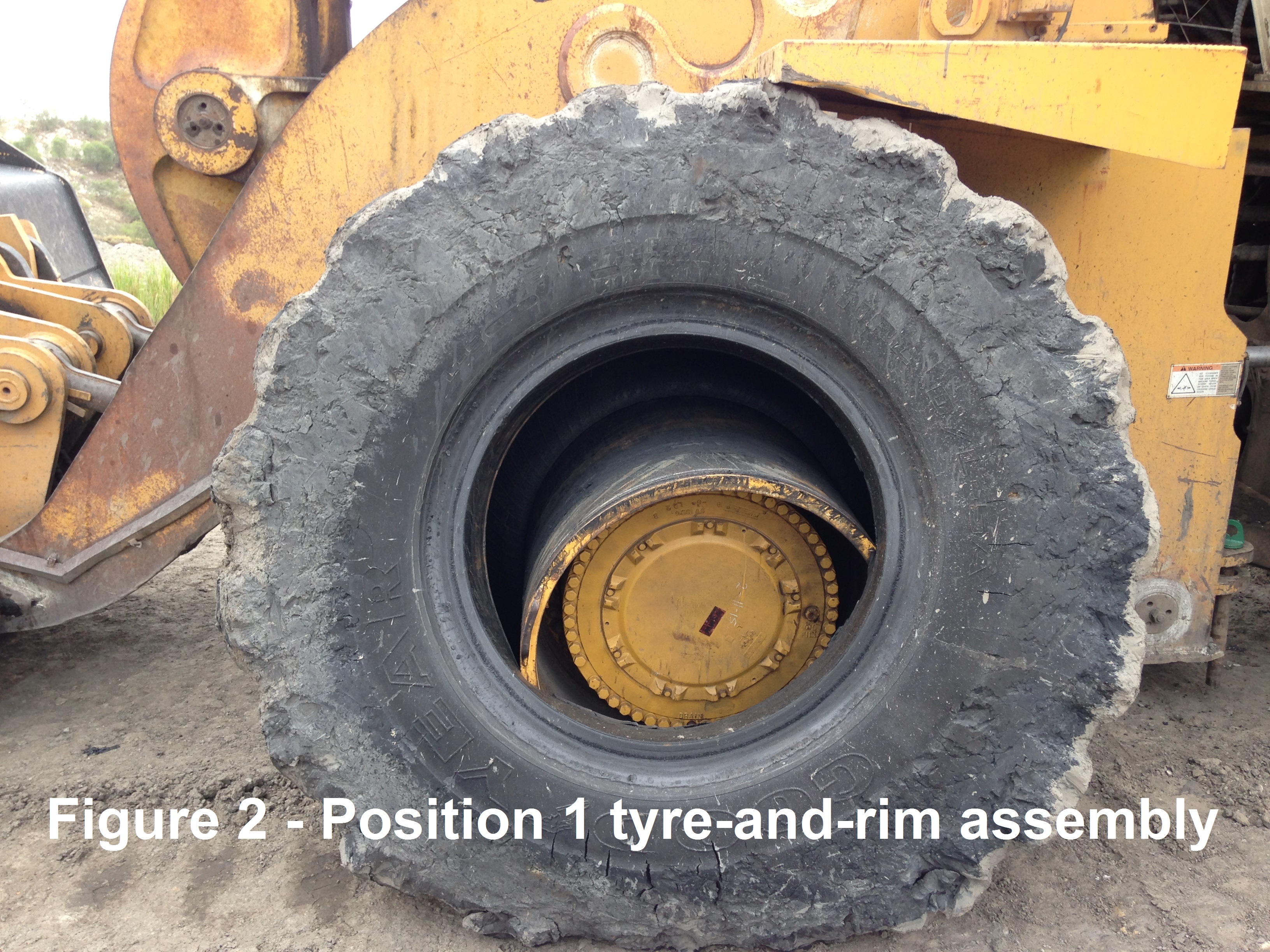
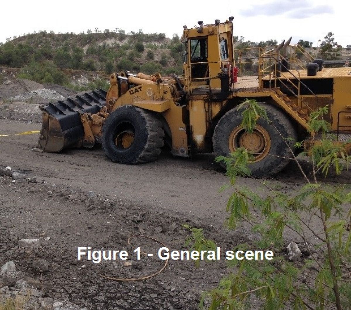
A Caterpillar 992C front end loader left the tyre bay after a new O-ring had been fitted to the position 1 tyre-and-rim assembly. After travelling approximately 100 metres, this same assembly failed catastrophically, resulting in parts being propelled up to 50 metres from the vehicle. No injuries occurred, despite the considerable potential for a serious injury or fatality (refer to Figures 1 & 2).
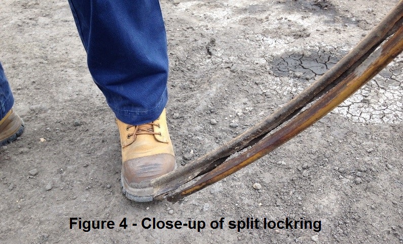
The lockring cracked circumferentially through the thinnest section, resulting in two “rings” that were no longer able to keep the assembly together (refer to Figures 3 & 4).
Lock ring
- Identification number LR45EM
- Approximately 1700 operating hours since new
Tyre size
- 45/65 - 45
Investigation
In an industry-led investigation, the incident was studied through a combined effort by the owner, the Original Equipment Manufacturer (OEM) and their local distribution agent, the University of Queensland Materials Performance (UQMP) section, and QMI.
A broad scope investigation was performed and highlighted both metallurgical and mechanical issues. The mechanical investigation included a finite element stress analysis. Relevant to this incident, the following items were determined:
- For the lifetime of the lock ring, the loader had been used for low duty applications near a coal handling and processing plant.
- The steel lock ring was manufactured through a process of cold drawing and rolling approximately three years prior and had been in operation for approximately 1700 hours at the time of failure.
- Early in the lock ring drawing process the steel was non-destructively tested (NDT) for defects. There was no other NDT prior to delivery to the client.
- The rim was 26 years old and the lock ring groove had significant, uneven levels of material loss from wear, corrosion and spalling.
- If the same amount of material loss in the lock ring groove had been uniformly distributed it would have increased the lock ring stress by less than 10%,
- However, the uneven wear in the lock ring groove, over an arc length of 300mm, increased stress on the lock rick ring by more than 500%. This stress level locally exceeded the steel's yield point and was a major contributor to the failure.
- Analysis has shown that the yield point can be reached if the deviation in lock ring groove wear depth is as little as 0.4mm over a groove length of 300mm.
- The lock ring failed circumferentially through a process of lamellar tearing.
- The lock ring contained a large quantity of non-metallic elongated manganese sulphide and other inclusions. These inclusions had a significant detrimental effect of the steel's through-thickness properties.
- The main stress direction was across the profile of the lock ring. Therefore, the direction of highest stress had the worst material properties.
- The material specification is Japanese Standard JIS G4051 S33C. Through-thickness properties were not specified.
The risk
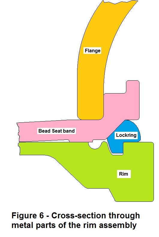
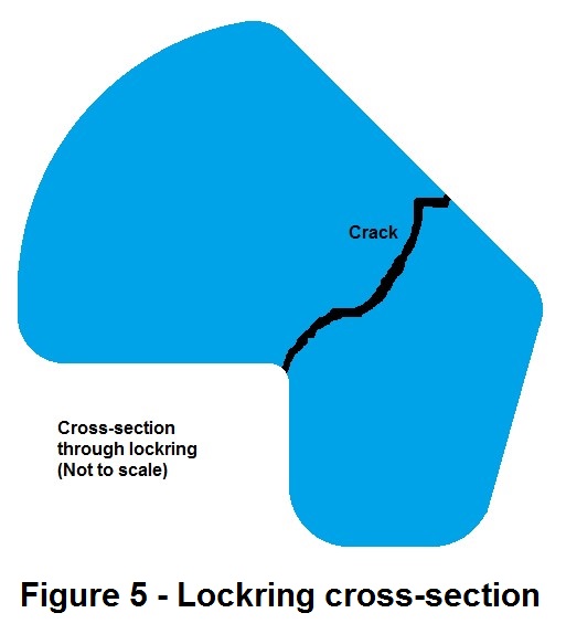
A large amount of energy is contained in the compressed air in a tyre. If this air is suddenly released, there is a significant risk of injury or fatality. This incident involved a 45" rim with an EM profile lock ring. Figures 5 and 6 show the lock ring and rim assembly cross-sections.
Conceptually it can occur on any pressurised tyre-and-rim assembly, regardless of the size, industry or type of vehicle. The recommendations in the next section should be considered for all applications, taking individual circumstances into account.
Second incident
A tyre on a Cat 992K Loader had developed a slow leak and was taken to the workshop for repair. Upon disassembly of the wheel, a tyre fitter identified a 590mm long circumferential crack in the rim's lock ring.
This incident was also investigated by UQMP, with their report being released recently. By using NDT techniques, they found a lot more cracking than what the fitter had initially seen. One of their findings is that the EM type lock ring operates at a small safety factor, thus there being an increased likelihood of a catastrophic disassembly if parameters change (e.g. operating conditions, corrosion, metal fatigue, damage or wear in the lock ring / rim groove).
Recommendations
Short term
- On a regular basis, inspect rim grooves and lock rings for wear, corrosion or spalling. Uneven material loss and excessive material loss are reasons for concern.
- Where designed to be fitted, install wheel rim locks to limit wear and differential movement between the metallic parts of the rim assembly.
- Metal parts, especially the lock ring groove must be thoroughly cleaned before assembly. Foreign contamination in the groove, such as dirt or corrosion products may load the lock ring unevenly, similar to an unevenly worn part.
- To help eliminate uneven loading, machining of rims and bead seat bands needs to be controlled within acceptable tolerances. Note, the quantification of machining tolerances and tolerances for material loss are specialised topics beyond the scope of this Safety Bulletin. For more information, consult a professional specialising in this field in conjunction with the OEM.
- An appropriate method of NDT needs to be applied at or near the final stage of manufacturing. NDT needs to be considered for lock rings already in use which have not been NDT after manufacturing.
Medium term
- Through-thickness mechanical properties need to be specified, especially for lock ring materials (e.g. steels with a 20% Short Transverse Reduction of Area or greater, as measured by ASTM A770, were found to be very resistant to lamellar tearing).
Long term
- The tyre-and-rim assembly involved in this incident is not designed to fail to a safe state. Designers and manufacturers are encouraged to consider this aspect in future designs. The goal should be to design a tyre-and-rim system such that if a failure occurs, it results in a controlled release of energy to a safe state.
Additional recommendations from second incident
- Investigate the possibility of upgrading to a lower stressed and therefore safer wheel design.
- Especially on older rims and lock rings, increase the frequency of crack inspections (NDT).
- Avoid the exposure of wheel assemblies to corrosive substances (e.g. saline water).
Background

Contact: Theo Kahl, Inspector of Mines , +61 7 4936 0127 QldMinesInspectorate@rshq.qld.gov.au
Issued by Resources Safety & Health Queensland
Find more safety notices
Search the hazards database